Custom Lidar Sensor Setup
: When using other Lidar other than the Lidar Sensor provided by the current simulator, the user can define and use Custom Lidar.
Currently, Custom Lidar is only available for ROS.
Create Custom Lidar Template File
After the template such as Custom’s Lidar’s name, Field of View, and Rotation Frequency is written as a json file format and placed in the corresponding directory, the simulator can use Custom Lidar following the template.
Template json file directory : SaveFile/LidarTemplate/*.json
Template json file example :
{
    "Name": "Lidar128",
    "LaserCount": 128,
    "MinDistance": 0.5,
    "MaxDistance": 245.0,
    "RotationFrequency": 10.0,
    "MeasurementsPerRotation": 1800,
    "FieldOfView": 40.0,
    "VerticalRayAngles": [ -11.742, -1.99, 3.4, -5.29, -0.78,
						4.61, -4.08, 1.31, -6.5, -1.11,
                        4.28, -4.41, 0.1, 6.48, -3.2,
                        2.19, -3.86, 1.53, -9.244, -1.77,
                        2.74, -5.95, -0.56, 4.83, -2.98,
                        2.41, -6.28, -0.89, 3.62, -5.07,
                        0.32, 7.58, -0.34, 5.18, -3.64,
                        1.75, -25, -2.43, 2.96, -5.73,
                        0.54, 9.7, -2.76, 2.63, -7.65,
                        -1.55, 3.84, -4.85, 3.18, -5.51,
                        -0.12, 5.73, -4.3, 1.09, -16.042,
                        -2.21, 4.06, -4.63, 0.76, 15,
                        -3.42, 1.97, -6.85, -1.33, -5.62,
                        -0.23, 5.43, -3.53, 0.98, -19.582,
                        -2.32, 3.07, -4.74, 0.65, 11.75,
                        -2.65, 1.86, -7.15, -1.44, 3.95,
                        -2.1, 3.29, -5.4, -0.01, 4.5,
                        -4.19, 1.2, -13.565, -1.22, 4.17,
                        -4.52, 0.87, 6.08, -3.31, 2.08,
                        -6.65, 1.42, -10.346, -1.88, 3.51,
                        -6.06, -0.67, 4.72, -3.97, 2.3,
                        -6.39, -1, 4.39, -5.18, 0.21,
                        6.98, -3.09, 4.98, -3.75, 1.64,
                        -8.352, -2.54, 2.85, -5.84, -0.45,
                        8.43, -2.87, 2.52, -6.17, -1.66,
                        3.73, -4.96, 0.43 ],
    "rotCorrections": [ 6.354, 4.548, 2.732, 0.911, -0.911, -2.732, -4.548, -6.354,
                        6.354, 4.548, 2.732, 0.911, -0.911, -2.732, -4.548, -6.354,
                        6.354, 4.548, 2.732, 0.911, -0.911, -2.732, -4.548, -6.354,
                        6.354, 4.548, 2.732, 0.911, -0.911, -2.732, -4.548, -6.354,
                        6.354, 4.548, 2.732, 0.911, -0.911, -2.732, -4.548, -6.354,
                        6.354, 4.548, 2.732, 0.911, -0.911, -2.732, -4.548, -6.354,
                        6.354, 4.548, 2.732, 0.911, -0.911, -2.732, -4.548, -6.354,
                        6.354, 4.548, 2.732, 0.911, -0.911, -2.732, -4.548, -6.354,
                        6.354, 4.548, 2.732, 0.911, -0.911, -2.732, -4.548, -6.354,
                        6.354, 4.548, 2.732, 0.911, -0.911, -2.732, -4.548, -6.354,
                        6.354, 4.548, 2.732, 0.911, -0.911, -2.732, -4.548, -6.354,
                        6.354, 4.548, 2.732, 0.911, -0.911, -2.732, -4.548, -6.354,
                        6.354, 4.548, 2.732, 0.911, -0.911, -2.732, -4.548, -6.354,
                        6.354, 4.548, 2.732, 0.911, -0.911, -2.732, -4.548, -6.354,
                        6.354, 4.548, 2.732, 0.911, -0.911, -2.732, -4.548, -6.354,
                        6.354, 4.548, 2.732, 0.911, -0.911, -2.732, -4.548, -6.354 ],
    "CenterAngle": 0.0,
    "TextureHeightFactor": 32,
    "TextureWeightFactor": 2
}
CODE
Custom Lidar Setting
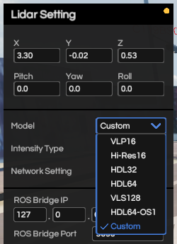
Like the given 3d Lidar, enter Sensor tab, select 3d Lidar, and add it.
Select “Custom” under “Model” item in Lidar Setting Panel.

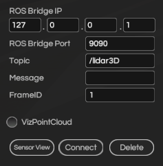
After entering ROS IP, PORT, FrameID and etc, clicking Connect, the user is able to use Custom Lidar as Ros. At this time, the default ROS message type is PointCloud2.

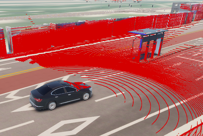
Custom Lidar’s visualization customized by the template file shown above.

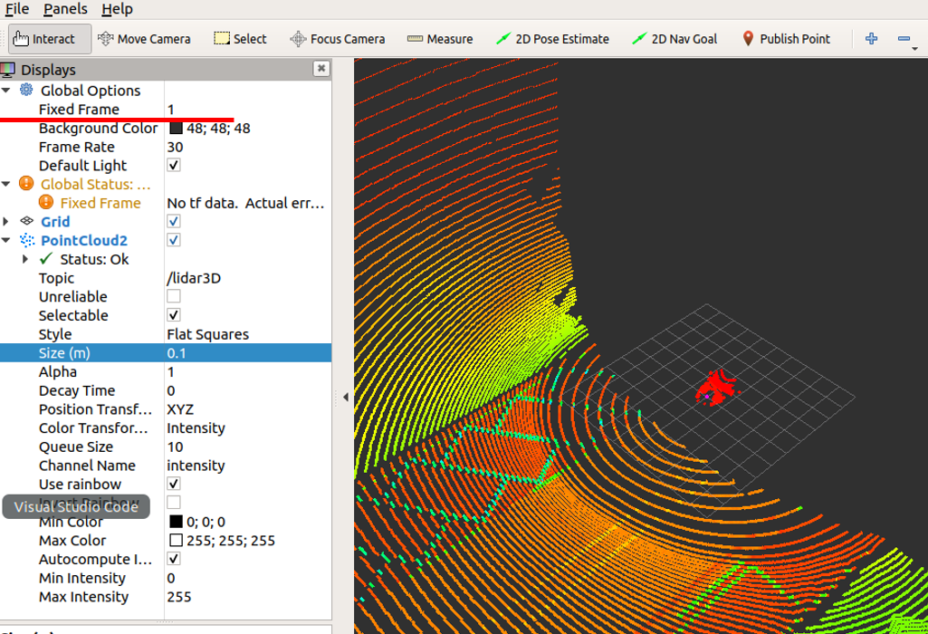
Visualization through Rviz. Like other Sensors, it can be received by ROS bridge.
It could be identified if entered properly on the Fixed Frame as shown on the Sensor Panel above.
